

Thermal Imaging Systems: How the Technology Really Works
Thermal imaging systems detect infrared radiation emitted by objects and convert that invisible heat energy into a visible image you can analyze in real time. Every object above absolute zero emits infrared radiation, and thermal cameras can detect objects warmer than −50°C (−58°F), making them effective in total darkness, dense smoke, and heavy fog where visible light cameras fail completely. The technology operates primarily in two wavelength bands: long-wave infrared (LWIR, 7–14 μm) and mid-wave infrared (MWIR, 3–5 μm), with most commercial and public safety cameras using the LWIR range.
At the core of any thermal imaging system are four components working in sequence:
- Optics: Specialized lenses made from materials like germanium or zinc selenide, since standard glass blocks infrared radiation entirely
- Detector: A focal plane array (FPA) that converts incoming infrared radiation into electrical signals
- Signal processing electronics: Circuits that amplify, correct, and digitize the raw detector output
- Display: A screen that renders the processed data as a color or grayscale thermal image
The result is a thermogram, a visual map of surface temperature differences across a scene. No external light source is needed. That independence from illumination is what makes infrared imaging technology so valuable across firefighting, industrial inspection, medical diagnostics, and defense.
How thermal energy and emissivity shape every thermal image
Understanding why a thermal image looks the way it does starts with two physical concepts: thermal energy and emissivity.
All matter above absolute zero constantly emits infrared radiation as a function of its temperature. The hotter an object, the more radiation it emits. But temperature alone does not determine how much radiation a thermal camera actually receives. The surface property called emissivity plays an equally large role.
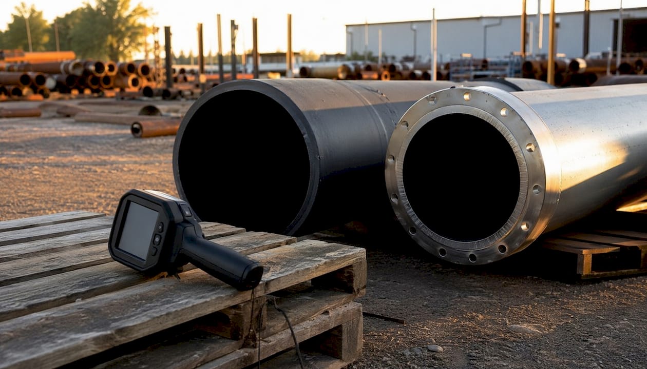
Emissivity is a dimensionless coefficient between 0 and 1 that describes how efficiently a surface emits infrared radiation compared to a perfect blackbody radiator (emissivity = 1.0). A matte black painted surface has an emissivity close to 0.95, meaning it radiates nearly as much as a perfect emitter at the same temperature. Polished aluminum, by contrast, has an emissivity as low as 0.05, so it emits very little of its own heat and instead reflects the infrared radiation of surrounding objects.
Key insight: Low-emissivity surfaces like polished metals appear artificially cool in a thermal image because the camera is reading reflected ambient radiation, not the metal’s actual temperature. This is one of the most common sources of measurement error in field thermography.
The practical consequence is significant. A thermal camera pointed at a stainless steel pipe may show a temperature significantly lower than the pipe’s actual surface temperature if emissivity is not corrected. Professionals address this by applying high-emissivity tape or matte coatings to the measurement spot, or by entering a known emissivity value into the camera’s software.
Emissivity values for common materials:
| Material | Approximate emissivity |
|---|---|
| Human skin | 0.98 |
| Matte black paint | 0.95 |
| Concrete | 0.92 |
| Oxidized steel | 0.70 |
| Polished copper | 0.03 |
| Polished aluminum | 0.05 |
Pro Tip: When measuring temperature on a low-emissivity surface in the field, apply a small strip of black electrical tape to the target area and measure the tape’s temperature instead. Electrical tape has an emissivity close to 0.95, giving you a far more accurate reading without any software adjustment.
A thermal camera does not simply read emitted radiation. It integrates three radiation sources simultaneously: emission from the target surface, reflection of ambient infrared from surrounding objects, and atmospheric attenuation along the optical path. Professional radiometric cameras apply the thermography equation to account for all three, which is why the output image represents an estimate of surface temperature rather than a direct measurement. Raw thermal images often have low contrast and fuzzy edges, and professional image processing including non-uniformity correction and pseudo-color enhancement is critical for producing actionable thermal data.
How infrared thermal imaging cameras actually work inside
A thermal camera is more than a sensor. Five components work together to turn invisible heat into a picture you can act on.
Optics
The lens system gathers infrared radiation from the scene and focuses it onto the detector array. Because infrared does not pass through standard glass, thermal camera optics use germanium or zinc selenide. Germanium is the most common choice for LWIR systems. Lens quality directly affects image sharpness, and in many professional systems the optics cost more than the detector itself.
The detector array
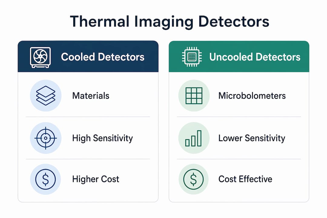
The detector is the heart of the camera. Modern systems use a focal plane array, a grid of individual sensing elements (pixels) that each respond to incoming infrared radiation. Two broad detector families dominate the market: cooled photon detectors and uncooled microbolometers.
Cooled detectors use materials like indium antimonide (InSb) or mercury cadmium telluride (HgCdTe) that must be chilled to cryogenic temperatures, typically using a miniature Stirling cycle refrigerator or liquid nitrogen. Cooling suppresses the detector’s own thermal noise, enabling extremely high sensitivity. The trade-off is size, cost, and mechanical complexity.
Uncooled microbolometers operate at or near ambient temperature. Each pixel is a tiny resistive element, often made from vanadium oxide (VOx) or amorphous silicon (a-Si), that changes resistance when heated by absorbed infrared radiation. The camera measures those resistance changes and maps them to temperature values. Uncooled sensors are smaller, lighter, and far less expensive than cooled alternatives, which is why they dominate commercial, public safety, and consumer applications.
Signal processing and image enhancement
Raw detector output is noisy and uneven. Non-uniformity correction (NUC) algorithms compensate for the fact that individual pixels in the array respond slightly differently to the same radiation level. Most cameras perform NUC automatically using an internal shutter that briefly blocks the scene and provides a uniform reference signal. After NUC, the camera applies pseudo-color palettes (iron, rainbow, grayscale) to map temperature values to visible colors, making temperature gradients easier to read at a glance.
Key performance metrics to understand:
- NETD (Noise Equivalent Temperature Difference): Measures thermal sensitivity. A value below 100 mK is the accepted standard for professional use.
- Spatial resolution: Defined by array size. A 160×120 pixel array is the practical minimum; 320×240 or larger is preferred for most inspection work.
- Dynamic range: Should be 60 dB or greater to handle scenes with wide temperature variation.
- Detector pitch: Pixel spacing of 60 microns or less achieves adequate sensitivity and resolution.
- Frame rate: Higher frame rates matter for moving targets; 30 Hz is standard for most applications.
Pro Tip: When comparing thermal cameras, NETD is the single most telling sensitivity spec. A camera rated at 50 mK will detect temperature differences that a 100 mK camera simply cannot resolve, which matters enormously in electrical panel inspections where a 2°C rise in a connector can signal impending failure.
What are the main types of thermal imaging detectors?
Thermal detectors divide into two major categories, with several specialty types serving niche roles. Cooled detectors offer higher sensitivity and faster response but require cryogenic cooling, making them larger and costlier. Uncooled detectors are more common in commercial and safety applications due to their compactness and reliability.
| System type | Detector technology | Sensitivity | Typical cost | Best use case |
|---|---|---|---|---|
| Cooled MWIR | InSb, HgCdTe | Very high | High | Military, scientific research |
| Cooled LWIR | HgCdTe, QWIP | Very high | High | Surveillance, defense |
| Uncooled LWIR | Microbolometer (VOx, a-Si) | Moderate | Low to moderate | Public safety, industrial, consumer |
| SWIR (short-wave IR) | InGaAs | High | Moderate to high | Solar cell inspection, material sorting |
| Pyroelectric | Pyroelectric ceramic | Moderate | Low to moderate | Motion detection, gas analysis |
Cooled systems are the choice when you need to detect extremely small temperature differences or when the target is at a great distance. Military targeting systems and scientific instruments almost always use cooled detectors. The cryogenic cooling adds startup time (sometimes up to 30 seconds), weight, and a maintenance burden from the refrigerator mechanism.
Uncooled microbolometers have become the workhorse of the industry. They start up quickly, run on battery power, and fit into handheld devices. The FLIR ONE, for example, is a consumer-grade uncooled module that attaches to a smartphone and uses FLIR’s patented MSX (Multi-Spectral Dynamic Imaging) technology to overlay visible-light detail onto the thermal image, making it practical for basic home inspection tasks. The Fluke PTi120 is a professional-grade uncooled camera aimed at electrical and mechanical maintenance technicians, offering a 120×90 detector array with a fixed focus lens suited for panel and equipment surveys.
SWIR detectors occupy a specialized niche. Short-wave infrared (0.9–1.7 μm) cameras using InGaAs arrays can image through certain plastics and detect moisture in materials, making them valuable in pharmaceutical quality control and solar panel inspection. They do not detect body heat and are not interchangeable with LWIR systems for most thermal applications.
Where thermal imaging technology gets used in the real world
The range of applications for heat detection systems is broader than most people realize, and it keeps expanding as sensor costs drop.
Firefighting is the most visible public safety use. Thermal imaging cameras let firefighters see through smoke, locate victims, and find the seat of a fire inside a structure without any visible light. Tennessee firefighters once used a thermal camera to detect a hidden fire inside a cinder railroad bed, resulting in an estimated $500,000 in avoided damage. Since 2003, NIOSH has recognized the absence of a properly used thermal camera as an avoidable contributing factor in firefighter injuries and deaths.
Electrical and mechanical maintenance is arguably the highest-volume professional application. Overheating connections, failing bearings, and overloaded circuit breakers all produce thermal signatures before they fail visibly. Detecting these anomalies early through preventive maintenance enables organizations to address problems before they cause downtime or fires.
Search and rescue operations use thermal imagers as force multipliers, allowing teams to cover large search areas rapidly and accurately with fewer personnel. A person lost in dense forest at night is nearly invisible to a standard camera but stands out clearly against a cool background in a thermal image.
Building diagnostics is a growing consumer and professional use. Thermal cameras reveal heat leaks through insulation gaps, moisture intrusion behind walls, and underfloor heating failures. The FLIR ONE and similar smartphone attachments have brought this capability to homeowners and property inspectors at a fraction of the cost of dedicated professional cameras. If you are exploring portable thermal options available in consumer electronics retail, Simlimsquareinsider covers compact thermal gadgets worth considering in 2026.
Surveillance and perimeter security benefit from thermal vision equipment’s ability to detect intruders in complete darkness without any illumination that could reveal the camera’s position. Thermal cameras are now routinely integrated into security systems alongside standard CCTV. For a deeper look at how thermal imaging fits into broader security setups, Simlimsquareinsider’s CCTV buying guide covers the integration points in detail.
Medical and veterinary screening uses thermal imaging to detect inflammation, circulatory abnormalities, and fever. During the 2004 SARS outbreak, Singapore and Hong Kong deployed thermal cameras at airports to screen travelers for elevated skin temperatures.
Drone-mounted inspection has become a fast-growing application. Solar farm operators now use thermal cameras on drones to detect underperforming panels. Where manual diagnostics would take weeks, drone-based thermal surveys take days.
Real-world impact: Thermal imagers serve as critical tools across firefighting, law enforcement, and industrial maintenance, providing actionable thermal data that is invisible to the naked eye and often impossible to obtain any other way.
Passive vs. active thermography: what the difference means in practice
Most people encounter passive thermography without realizing it has a name. In passive thermography, the camera simply detects the natural thermal contrast that already exists between a target and its background. No external energy source is needed. Surveillance cameras watching a parking lot at night, firefighters searching a burning building, and doctors screening for inflammation all use passive thermography.
Active thermography requires an external energy source to create a temperature difference between the feature of interest and its background. The inspected object is typically in thermal equilibrium with its surroundings, so natural contrast is too low to detect subsurface defects. By briefly heating the surface with a flash lamp, ultrasonic transducer, or induction coil, technicians create a transient thermal gradient that reveals hidden cracks, delaminations, or voids as the heat diffuses unevenly through the material.
Active thermography is the standard method for nondestructive testing (NDT) of aerospace composites, carbon fiber structures, and bonded assemblies. An aircraft wing panel with a subsurface disbond will cool at a different rate than the surrounding intact material, and a thermal camera captures that difference within seconds of the heat pulse.
Key distinctions between the two approaches:
- Passive: No external energy source; detects naturally occurring temperature differences; used in surveillance, medical screening, building inspection, and firefighting
- Active: Requires controlled energy input; detects subsurface features and material defects; used in NDT, aerospace, and manufacturing quality control
- Pulsed thermography: A short, intense heat pulse followed by rapid thermal image capture; best for thin materials
- Lock-in thermography: Periodic heating with phase-sensitive detection; better for deeper defects and quantitative analysis
Video fusion is an emerging technique that combines thermal and visible-spectrum images with adjustable blending. Video fusion technology overlays thermal and CCD color images, letting the operator slide between 100% thermal and 100% visible, or any blend in between. At the right blend ratio, details like license plate numbers remain readable while the thermal context is preserved. Notably, this technology also allows viewing through glass, which standard thermal cameras cannot do.
Pro Tip: For building envelope inspections, always use passive thermography during a temperature differential of at least 10°C between inside and outside. A smaller differential produces thermal contrasts too subtle for most uncooled cameras to resolve reliably.
How to choose the right thermal imaging camera for your needs
Selecting a thermal camera comes down to matching the detector’s capabilities to the demands of your specific application. A camera that excels at firefighting is not necessarily the right tool for precision industrial measurement.
Step 1: Define your primary application
The application determines the wavelength band, sensitivity requirement, and form factor. Firefighting and search and rescue need rugged, handheld LWIR cameras with fast startup times. Electrical maintenance needs a camera with a temperature measurement range that covers at least 350°C and software that can generate inspection reports. Scientific research may require a cooled detector with NETD below 20 mK.
Step 2: Evaluate detector resolution
A 160×120 pixel array is the minimum for effective use; 320×240 is the practical standard for professional inspection work. Higher resolutions (640×480 and above) are available in premium systems and matter when you need to identify small thermal anomalies at distance.
Step 3: Check thermal sensitivity (NETD)
For most professional applications, NETD below 100 mK is the accepted threshold. Cameras rated at 50 mK or lower give you the ability to detect subtle temperature gradients that lower-sensitivity cameras miss entirely.
Step 4: Consider portability and power
Handheld uncooled cameras like the Fluke PTi120 run on rechargeable batteries and weigh under a kilogram, making them practical for field technicians. Cooled systems are heavier, require startup time, and consume more power. For consumer use, smartphone attachments like the FLIR ONE eliminate the need for a dedicated device entirely and can be enhanced with accessories such as the Logitech Reach Camera Clamp Mount Accessory to improve usability.
Step 5: Assess software and reporting capabilities
Professional thermal cameras come with analysis software that lets you set isotherms, measure spot temperatures, and generate PDF reports with annotated images. For maintenance programs, software compatibility with your existing asset management system matters as much as the camera’s hardware specs.
Selection checklist:
- Detector type: cooled vs. uncooled, based on sensitivity requirement
- Array resolution: 160×120 minimum, 320×240 or higher preferred
- NETD: below 100 mK for professional use
- Temperature measurement range: must cover your target temperature band
- Lens options: fixed vs. interchangeable, field of view
- Operating environment: IP rating, temperature range, drop resistance
- Software: reporting, emissivity correction, isotherm tools
- Budget: uncooled systems range from consumer-grade attachments to professional field cameras; cooled systems carry a significant price premium
For readers exploring portable thermal solutions available through consumer electronics retailers, Simlimsquareinsider’s guide to mobile alternatives covers compact options worth evaluating alongside dedicated thermal cameras.
What thermal imaging technology cannot do
Thermal imaging is genuinely powerful, but it has hard physical limits that every user needs to understand before relying on it for critical decisions.
It cannot see through glass or water. Thermal imaging cannot look through glass or water because these materials absorb long-wave infrared radiation. Point a thermal camera at a window and you will see a reflection of the scene behind you, not the room on the other side. This is a fundamental physical constraint, not a limitation of camera quality.
Resolution is lower than visible light cameras. Most uncooled thermal cameras top out at 320×240 pixels in the mid-range and 640×480 in professional models, compared to the multi-megapixel sensors in standard cameras. Fine spatial detail is simply not available. Two objects at the same temperature will appear identical regardless of their shape or color.
Emissivity variability causes measurement errors. As covered earlier, low-emissivity surfaces reflect ambient infrared and appear cooler than they actually are. Without emissivity correction, absolute temperature readings on metallic surfaces can be significantly wrong.
Microbolometers need regular recalibration. Microbolometer sensors require routine recalibration because they respond to both external radiation and their own internal heat. Most cameras handle this automatically with an internal shutter, but the shutter mechanism adds a brief interruption to the image stream and can wear over time.
Environmental factors degrade performance. Rain, high humidity, and extreme ambient temperatures all affect image quality. Reflective surfaces in the scene, such as metal walls or puddles, can create false hot spots through infrared reflection. Wind cools surfaces and reduces the thermal contrast between a heated anomaly and its background.
Key limitations at a glance:
- Cannot see through glass, water, or most liquids
- Lower spatial resolution than visible-light cameras
- Emissivity errors on metallic or reflective surfaces
- Requires periodic recalibration (automatic in most modern cameras)
- Susceptible to reflections from nearby heat sources
- Depth perception is poor, increasing the risk of tripping or misjudging distances in navigation use
- Startup time on cooled systems can reach 30 seconds
Advanced sensor calibration and image enhancement techniques
Getting accurate, repeatable thermal data from a camera requires more than pointing it at a target. The sensor architecture and image processing pipeline both introduce errors that calibration and enhancement techniques are designed to correct.
Non-uniformity correction
Every pixel in a focal plane array has a slightly different response to the same radiation level. Without correction, the image shows a fixed-pattern noise that looks like a faint grid or texture overlaid on the scene. NUC algorithms measure each pixel’s offset and gain against a uniform reference (the internal shutter) and apply per-pixel correction coefficients. Most cameras perform NUC automatically every few minutes or when the ambient temperature shifts.
Emissivity correction methods
Beyond applying coatings in the field, professional thermal cameras allow the operator to enter a known emissivity value for the target material. The camera’s radiometric software then adjusts the temperature calculation accordingly. For surfaces with unknown emissivity, emissivity correction techniques such as applying high-emissivity coatings or tape provide a reference point for accurate measurement.
Microbolometer recalibration
Microbolometer drift is an ongoing challenge. The sensor’s own temperature changes as the camera warms up during use, shifting the baseline for all measurements. Internal shutter mechanisms provide a periodic flat-field reference, but software offset techniques can also compensate for drift between shutter events. This is a maintenance practice that users often overlook, yet it directly affects the accuracy of temperature readings over a long inspection session.
High-resolution UFPA development
Current improvements in uncooled focal plane arrays focus on higher sensitivity and pixel density. DARPA announced a five-micron LWIR camera using a 1280×720 focal plane array, a resolution that was previously available only in cooled systems. Smaller pixel pitch means more pixels per unit area, which translates directly to finer spatial resolution without increasing the physical size of the detector.
Multispectral image fusion
Fusing thermal data with visible-light or near-infrared imagery produces images that combine the temperature sensitivity of thermal cameras with the spatial detail of standard cameras. The FLIR ONE’s MSX technology is a consumer implementation of this principle. At the professional end, multispectral fusion platforms used in aerial surveillance and industrial inspection can overlay thermal anomalies onto high-resolution visible maps, making it far easier to localize a problem precisely.
Key enhancement and calibration techniques:
- Non-uniformity correction (NUC) via internal shutter reference
- Per-pixel gain and offset calibration stored in camera firmware
- Emissivity adjustment through software input or field coatings
- Microbolometer drift compensation using software offset algorithms
- Pseudo-color palette mapping for temperature gradient visualization
- Multispectral fusion with visible or NIR imagery for spatial detail
- Spatial filtering and edge enhancement for sharper thermogram boundaries
Pro Tip: After any significant change in ambient temperature, give your uncooled camera at least five minutes to thermally stabilize before taking critical measurements. The internal NUC shutter corrects for gross drift, but the camera’s housing and optics need time to reach equilibrium for the most accurate readings.
Thermal camera performance specifications summary:
| Parameter | Minimum standard | Professional standard |
|---|---|---|
| Array resolution | 160×120 pixels | 320×240 pixels or higher |
| NETD | Below 100 mK | Below 50 mK |
| Dynamic range | 60 dB | 60 dB or greater |
| Detector pitch | 60 microns or less | — |
| Startup time (uncooled) | Under 5 seconds | Under 5 seconds |
| Startup time (cooled) | Up to 30 seconds | Up to 30 seconds |
Explore thermal imaging gear at Sim Lim Square
Sim Lim Square in Singapore carries a wide selection of thermal imaging cameras, smartphone attachments, and related electronics across its retail floors. Whether you are looking for a consumer-grade FLIR ONE module for home inspections or a professional-grade camera for maintenance work, the stores at Sim Lim Square let you handle the hardware in person, compare models side by side, and get advice from knowledgeable staff before you buy. The Basement 1 stores are a strong starting point for electronics and imaging equipment, with vendors offering local warranty support and in-store product testing.
Key Takeaways
Thermal imaging systems detect infrared radiation to produce heat maps that work in total darkness, smoke, and fog, with accuracy depending heavily on emissivity correction, detector type, and regular sensor calibration.
| Point | Details |
|---|---|
| Wavelength bands matter | Most commercial cameras operate in the LWIR range (7–14 μm); MWIR systems offer higher sensitivity for specialized use. |
| Emissivity drives accuracy | Low-emissivity surfaces like polished metals appear artificially cool; apply coatings or enter a known emissivity value to correct readings. |
| Uncooled vs. cooled detectors | Uncooled microbolometers suit most commercial and safety applications; cooled detectors deliver higher sensitivity for military and scientific work. |
| Resolution minimums | A 160×120 pixel array is the minimum for effective use; 320×240 or larger is the professional standard for inspection work. |
| Calibration is ongoing | Microbolometer sensors require routine recalibration because they respond to their own internal heat as well as external radiation. |
FAQ
What are the three main types of thermal imaging technology?
The three primary types are cooled photon detectors (using InSb or HgCdTe arrays requiring cryogenic cooling), uncooled microbolometers (operating at ambient temperature using VOx or a-Si resistive elements), and pyroelectric sensors (which respond to changes in radiation rather than absolute levels). Cooled detectors offer the highest sensitivity; uncooled microbolometers dominate commercial and public safety applications.
Can a smartphone do thermal imaging on its own?
Standard smartphones cannot detect infrared radiation because their CMOS sensors are designed for visible light. Attachments like the FLIR ONE add an uncooled microbolometer module that connects via USB-C or Lightning, giving the phone genuine thermal imaging capability for tasks like home inspection and energy audits.
What is the best thermal imaging camera for most users?
For professional electrical and mechanical maintenance, the Fluke PTi120 offers a practical balance of resolution, ease of use, and reporting software. For consumer and light inspection use, the FLIR ONE provides solid thermal performance in a compact smartphone attachment. For firefighting and search and rescue, purpose-built ruggedized cameras designed to meet industry standards are the appropriate choice.
What is the difference between FLIR and thermal imaging?
FLIR (Forward Looking Infrared) is a brand name and a term originally used for airborne infrared sensor systems, now widely associated with the company FLIR Systems and its product line. Thermal imaging is the broader technology category. All FLIR cameras are thermal imaging devices, but thermal imaging cameras are made by many manufacturers beyond FLIR.
Why can’t thermal cameras see through glass?
Glass absorbs long-wave infrared radiation rather than transmitting it, so a thermal camera pointed at a window captures only the glass surface temperature and a reflection of the surrounding scene. Thermal imaging cannot see through glass or water for this physical reason. Video fusion technology, which overlays thermal and visible-light images, is the current workaround for scenarios where glass penetration would otherwise be needed.
Recommended
- CCTV Security Systems: Your Complete Buying Guide – Sim Lim Square Insider
- Master the workflow for finding tech deals at Sim Lim Square – Sim Lim Square Insider
- Best Graphics Cards in 2024: Your Complete Buying Guide – Sim Lim Square Insider
- How to find the best tech deals at Sim Lim Square – Sim Lim Square Insider